Category : Cisco Wireless
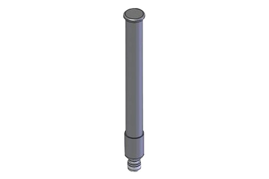
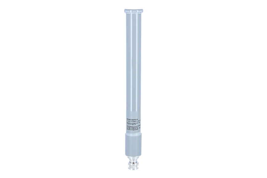
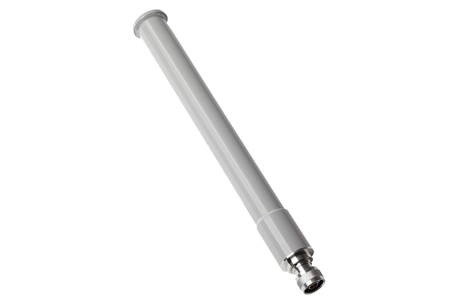
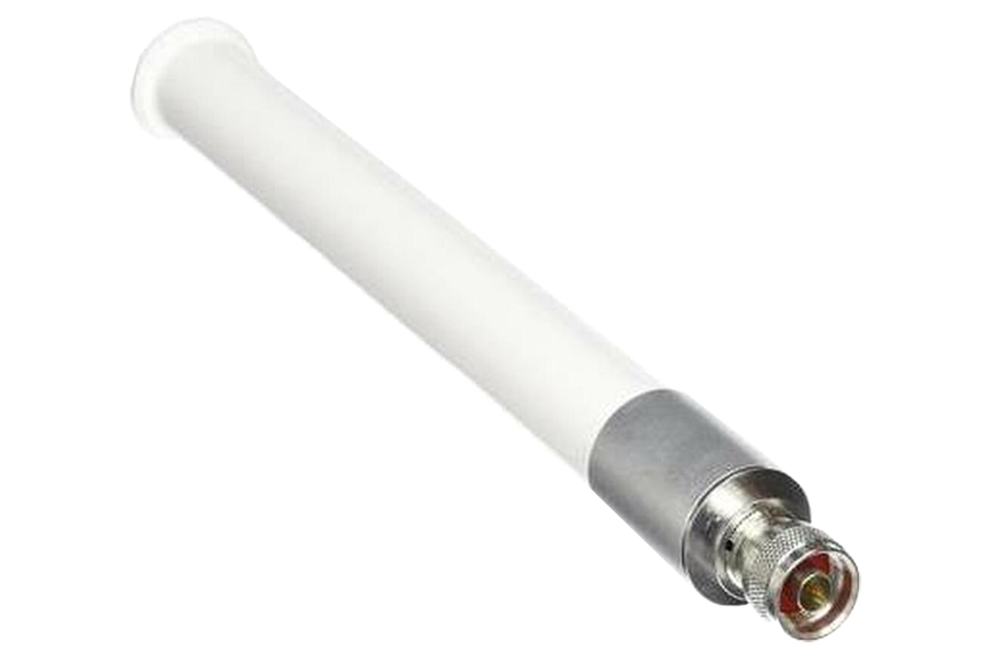
Cisco Aironet Dual-Band Omnidirectional Antenna (AIR-ANT2547VG-N)
Cisco Aironet 1560 Series Outdoor Access Point
Enquiry Us Contact NowCisco Aironet Dual-Band Omni-Directional Antenna (AIR-ANT2547VG-N)
Note: The documentation set for this product strives to use bias-free language. For purposes of this documentation set, bias-free is defined as language that does not imply discrimination based on age, disability, gender, racial identity, ethnic identity, sexual orientation, socioeconomic status, and intersectionality. Exceptions may be present in the documentation due to language that is hardcoded in the user interfaces of the product software, language used based on RFP documentation, or language that is used by a referenced third-party product.
This describes the Cisco Aironet AIR-ANT2547VG-N dual-band omni-directional antenna, and provides specifications and mounting instructions. The antenna is designed for outdoor use with Cisco Aironet Outdoor Access Points (hereafter referred to as access points) with radios operating in the 2.4 GHz and 5 GHz frequency bands.
These topics are discussed:
Technical Specifications
- Antenna type : Omni-directional collinear array
- Operating frequency range :
- 2400–2483 MHz
- 5150–5875 MHz
- 2:1 VSWR bandwidth :
- 2400–2483 MHz
- 5150–5875 MHz
- Nominal input impedance :
- 50 Ohms
- Gain (2400–2483 MHz) : 4-dBi
- Gain (5250–5875 MHz) : 7-dBi
- Polarization : Linear
- E-plane 3-dB beamwidth :
- 2.4 GHz: 30°
- 5 GHz: 14°
- H-plane 3-dB bandwidth : Omni-directional
- Length : 11.1 in. (28.2 cm)
- Diameter : 1.25 in. (3.17 cm)
- Weight : 6.0 oz. (170.0 g)
- Connector type : N-Male
- Operating temperature :
- -40–185°F
- (-40–85°C)
- Water/Foreign Body Ingress : IP66, IP67
- Wind rating :
- 100 mph (161 kph) operational
- 165 mph (265 kph) survival
System Requirements
This antenna is designed for use with the Cisco Aironet Outdoor Access Points.
Safety Precautions
Warning: Do not locate the antenna near overhead power lines or other electric light or power circuits, or where it can come into contact with such circuits. When installing the antenna, take extreme care not to come into contact with such circuits, as they may cause serious injury or death. For proper installation and grounding of the antenna, please refer to national and local codes (e.g. U.S.: NFPA 70, National Electrical Code, Article 810, Canada: Canadian Electrical Code, Section 54). Statement 280
- For your safety, read and follow these safety precautions.
- Before you install an antenna, contact your Cisco account representative to explain which mounting method to use for the size and type of antenna that you are about to install.
- Find someone to help you—installing an antenna is often a two-person job.
- Select your installation site with safety, as well as performance, in mind. Remember that electric power lines and phone lines look alike. For your safety, assume that any overhead line can kill you.
- Contact your electric power company. Tell them your plans and ask them to come look at your proposed installation.
- Plan your installation carefully and completely before you begin. Each person involved in an installation should be assigned to a specific task and should know what to do and when to do it. One person should be in charge of the operation to issue instructions and watch for signs of trouble.
- When installing your antenna, follow these guidelines:
- Do not use a metal ladder.
- Do not work on a wet or windy day.
- Dress properly: Wear shoes with rubber soles and heels, rubber gloves, and a long-sleeved shirt or jacket.
- If the assembly starts to drop, move away from it and let it fall. Because the antenna, mast, cable, and metal guy wires are all excellent conductors of electrical current, even the slightest touch of any of these parts to a power line completes an electrical path through the antenna and the installer.
- If any part of the antenna system should come in contact with a power line, do not touch it or try to remove it yourself. Call your local power company to have it removed safely.
- If an accident should occur with the power lines, call for qualified emergency help immediately.
Installation Notes
The antenna is designed to connect to a dedicated antenna port on the access point. No special tools are required to install the antenna.
The antenna is resistant to the full range of outdoor environments. After the antenna is attached to the access point, seal the connections to prevent moisture and other weathering elements from affecting performance. Cisco recommends using a coax seal (such as CoaxSeal) for outdoor connections. Silicone sealant or electrical tape are not recommended for sealing outdoor connections.
Choosing a Mounting Location
The antenna is designed to create an omni-directional broadcast pattern. To achieve this pattern, the access point should be mounted clear of any obstructions to the sides of the radiating element. If the mounting location is on the side of a building or tower, the antenna pattern is degraded on the building or tower side.
Generally, the higher an antenna is above the ground, the better it performs. A practice is to install your antenna about 5 to 10 ft (1.5 to 3 m) above the roof line and away from all power lines and obstructions.
Tools and Equipment Required
No tools are required to mount the antenna to the access point. However, you may need a ¾-in. (19 mm) open end or combination wrench (or adjustable wrench) to remove the antenna port covers.
For information about tools required to mount the access point, see the appropriate access point documentation.
Mounting the Antenna
To connect the antenna to the access point:
- If necessary, remove the antenna port cover.
- Align the antenna’s N-type connector with the appropriate antenna port.
- Gently push the antenna into the port.
- Hand tighten the antenna to the port using the metal knurled ring only.
Warning: Do not use the plastic body to tighten. This may damage the antenna.
Communications, Services, and Additional Information
- To receive timely, relevant information from Cisco, sign up at Cisco Profile Manager.
- To get the business impact you’re looking for with the technologies that matter, visit Cisco Services.
- To submit a service request, visit Cisco Support.
- To discover and browse secure, validated enterprise-class apps, products, solutions and services, visit Cisco Marketplace.
- To obtain general networking, training, and certification titles, visit Cisco Press.
- To find warranty information for a specific product or product family, access Cisco Warranty Finder.